Model: EN-LTC-DALI
The tunnel lighting control and monitoring system is operated and installed in accordance with the CIE 88-2004 requirements.
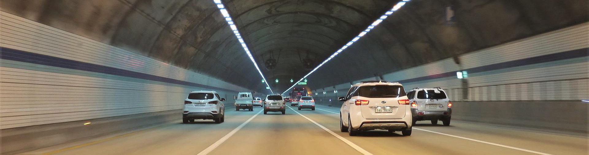
Adjusting the artificial lighting’s intensity at the entrance to the tunnel to the natural lighting intensity outside, is critical for the driver’s eye adaptation.
The lighting intensity is adjusted according to the standard requirements.
In order to adjust the lighting intensity, a dedicated optical sensor (luminance meter) is installed in front of the tunnel’s entrance. This sensor linearly converts the measured light intensities to a 4-20mA signal. This signal connects to a dedicated lighting controller for this purpose. The lighting controller makes the required changes in the lighting intensity in accordance with the signal received 4-20mA from the optical sensor.
The changes in the lighting intensity can be made in one of the following methods:
- Switching the lighting fixtures on and off, at predetermined degrees, as customary with LED lights,
- Dimming the lighting linearly, as possible with lighting fixtures in LED technology,
- Combination of the two methods indicated above, in accordance with the design requirements.

The lighting control system includes a dedicated integrated backup that ensures the lighting’s ongoing proper functioning in the event of a failure in the optical sensor unit. The dedicated backup system is based on a real-time clock and an astronomical clock. The backup system will ensure the drivers’ safety and prevent waste of energy until the failure of the optical sensor unit is removed.
The transition to LED technology lighting fixtures allows to control lighting intensities linearly, at the single flashlight level, while reducing the number of accessories and physical size of the lighting fixtures’ electrical panels installed in the tunnel. This allows significant savings in energy consumption and installation costs relative to other control methods.
System description:
The system includes a PC computer and a dedicated tunnel lighting management software. The lighting control system is based on the DALI communication protocol in accordance with the IEC 62386 requirements and enables operation and control of all lighting fixtures that include a DALI communication interface.
The system allocates digital addresses to all lighting fixtures automatically, so that each lighting fixture has an address in the system that is integrated with the lighting fixture number according to the lighting program of the tunnel.
Control of the lighting fixtures, dimming, switching on and off is made possible by means of communication commands without the need for electrical disconnection of the lighting fixtures.
The lighting controller enables the lighting fixtures to be switched on and off (in whole or in part) in accordance with the design requirements and in accordance with the signals received from the luminance meter unit and/or the backup unit operating on an astronomical time and clock basis. The lighting fixtures’ operation is available at any lighting intensity required, for each lighting fixture (0-100%) and in accordance with the design requirements.
The system performs automatic monitoring of faults in the lighting fixtures and infrastructure and will detect faulty lighting fixtures, communication faults between the lighting fixtures and disconnected cables.
When detecting faults in the lighting fixtures and/or cables, the system performs the following actions:
Luminance meter backup:
The system includes an integral control unit for detecting faults in the luminance meter unit, and when a fault is detected in the luminance meter, the system performs the following actions:
Control and communication system:
The system includes 20 DALI communication channels controlling the lighting fixtures’ 1,280 digital addresses (the amount of digital addresses can be expanded to 256 addresses per module).
The lighting controller includes:
- 4-20mA linear signal input adapted to the luminance meter unit, setting the maximum and minimum power, in accordance with the design requirements.
- Dedicated software adjusting the lighting intensity in the tunnel to the signal received from the luminance meter unit.
Integral dedicated software for backing up and controlling the lighting in the event of a fault in the luminance meter sensor, based on a real-time clock and an astronomical clock.
- Active protection against fault voltage is installed on each of the communication channels’ outputs on the communication line.
The system is operated using a PC unit and dedicated management software that enables the operation of each luminaire separately or the operation of groups of fixtures for the purpose of adjusting the lighting intensity in the tunnel to design requirements.
System’s max. measurements:
Central electrical and control system cabinet: width: 60 cm, height: 80 cm, depth: 25 cm.
Control software:
The control software is used to monitor and control the lighting fixtures, using a communication interface to the dedicated computer. The software can perform the following control and monitoring operations:
- Allocation of DALI addresses to all lighting fixtures.
- Displaying the lighting fixtures’ status – normal and incorrect, including the display of their address and location.
- Displaying the fixtures’ calibration status for all lighting fixtures.
- Displaying communication faults and disconnected cables.
- Operation screens and more.
Control software functions:
- Sending a fault message by email.
- files saving during a power outage.
- Automatic return to full operation after returning from a power outage.
The system’s computer unit includes communication interfaces: RS232, USB, TCP / IP.
The communication interface enables the transmission of fault and correctness indicators to other control systems, in the MODBUS protocol, used by the facility, including activating the lighting proactively.
The communication interface allows the reception of a signal of 4-20mA, from the luminance meter unit, for the purposes of lighting, switching off and dimming the lighting fixtures.
For a control and monitoring system consulting/planning for for Tunnel lighting, please leave details and our representative will get back to you soon.